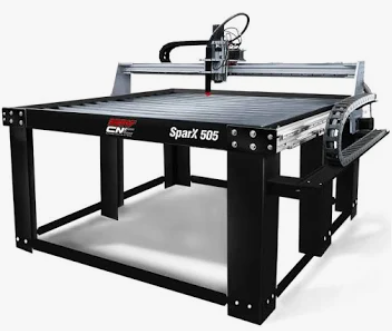
Two machines, two jobs
STV’s SparX 505 page describes a 5x5 plasma table with MyPlasmCNC as standard control, with DXF among its inputs. An optional OptimumCNC controller is described as a Linux MiniPC that accepts DXF as well as .gcode, .nc and .tap files, and more.
TableCAD remains a Windows program. It does not run on the table’s Linux computer, and that is fine, because the design stage does not need to live there. Draw on a Windows PC, then transfer the file to the table computer by whatever method your shop uses.
Why separation helps
A modular table is a set of choices: controller, torch, height control, accessories. The more your hardware varies, the more valuable it is to keep drawing independent of it. A DXF drawn once serves any controller that reads DXF, and it survives an upgrade.
TableCAD handles the design side, with exact dimensions, holes, slots, text, bolt circles, combine and align tools, inches or millimeters, and unlimited undo. When it is time to plan the cut, it can show holes-first order, kerf compensation and lead-ins in simulation.
DXF handoff or verified G-code
There are two honest routes. The first is DXF: export from TableCAD, load it in the controller’s own import, and let that software handle toolpaths. This is the route the published inputs most plainly support.
The second is G-code from TableCAD, appropriate only after its format and configuration have been verified for your particular controller. This guide does not supply post-processor settings or claim universal compatibility; confirm against your controller’s manual and a dry run with the torch off, following STV’s guidance.
A transfer routine worth keeping
File transfer is where careless mistakes creep in. Use one folder per job, include units and material in the name, and archive superseded revisions separately from the active cut files. When the file opens, compare its preview to the drawing: overall size, hole count, and origin should match what you drew.
If something looks wrong, go back to the drawing, not the controller. Fixing geometry upstream and re-exporting keeps both programs simple.
Workflow map
Design PC to table computer
- TableCAD · designDraw on the Windows PCExact parts, DXF import, units.
- TableCAD · prepPlan and simulateHoles first, kerf, lead-ins, G-code preview.
- HandoffExportDXF, or G-code only if verified for your controller.
- HandoffTransfer filesMove to the table computer by your usual method.
- Machine sideController previewMyPlasmCNC or OptimumCNC loads and previews.
Preflight before you cut
Confirm your machine and configuration, and keep the manufacturer’s manual open for the controller-specific steps.
- Identify whether the table uses MyPlasmCNC or the optional OptimumCNC.
- Confirm accepted file types in the controller documentation.
- Dry run with the torch disabled where the manual describes one.
- Compare size, holes and origin in the preview to the drawing.
External sources
Official pages used for brand-specific facts in this guide:
TableCAD is independent software and is not affiliated with, endorsed by, or sponsored by Langmuir Systems, ArcLight, Torchmate / Lincoln Electric, STV, WAZER, Flow, OMAX, Laguna, Jet Edge, WARDJet, Techni Waterjet, or any other table or waterjet manufacturer referenced on this site. All manufacturer names, product names, trademarks and controller names belong to their respective owners and are used only to describe compatibility and workflow context.